ESP32C3SuperMini Pin Usage
ESP32C3SuperMini has rich interfaces. There are 11 digital I/O pins that can be used as PWM pins, and 4 analog inputs that can be used as ADC pins. It supports four serial communication interfaces including UART, I2C, SPI, and I2S. This article will help you understand these interfaces and implement them in your next project!
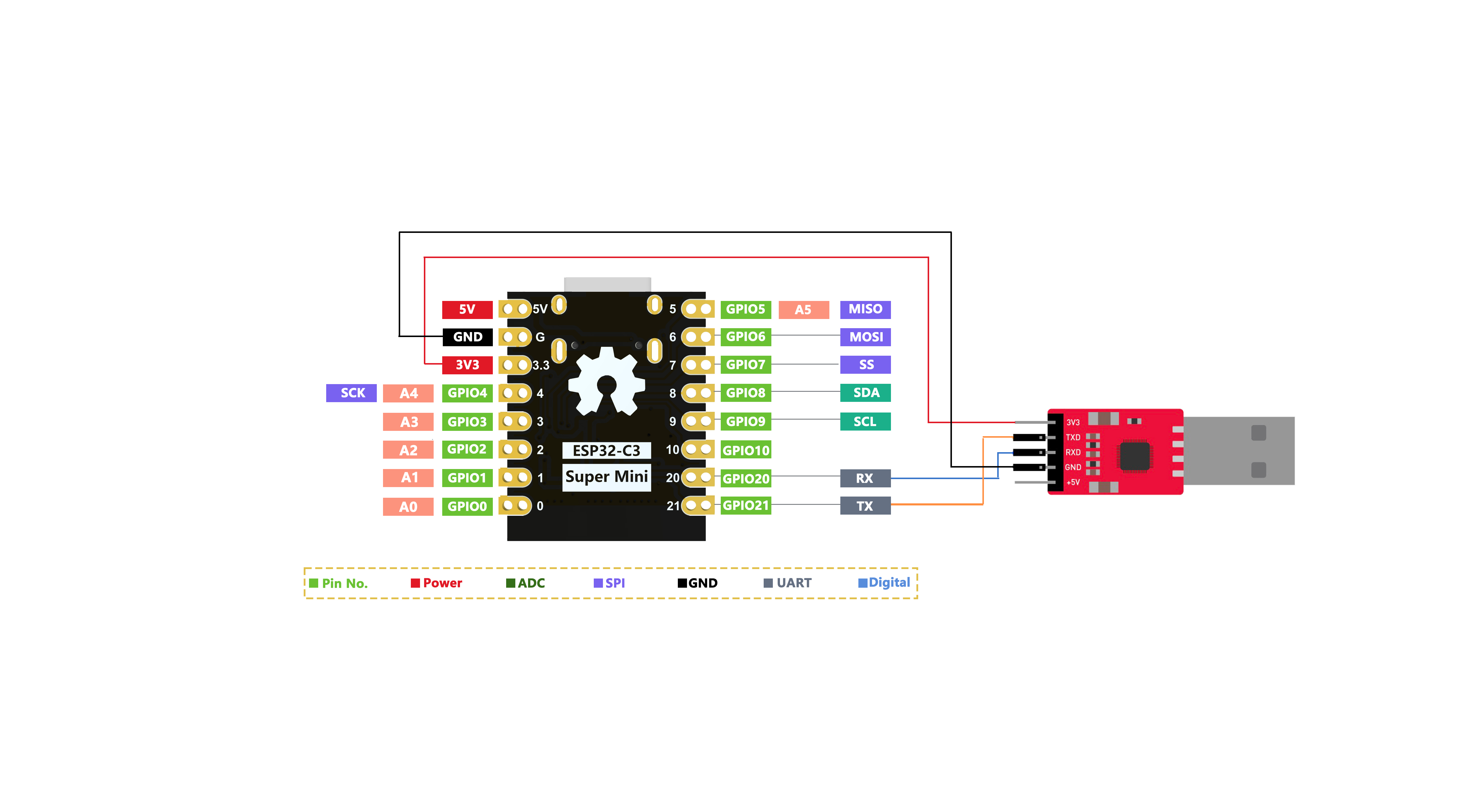
Regarding pins A0~A5, GPIO0~GPIO10 (0~10), and those starting with D, let me explain here. By default, the main board only has GPIO pins, which are 0~10, 20, 21. The appearance of A0~A5 pins is a mapping issue, designed to conveniently tell users whether the function of this pin is analog or digital. When selecting the board type in Arduino, choose "ESP32C3 Dev Module", and you can reference its pin mapping. The pin mapping diagram is as follows.

Digital Pins
Upload the following code to the board, and the on-board LED will turn on and off every second.
// define led according to pin diagram
int led = 8;

void setup() {
  // initialize digital pin led as an output
  pinMode(led, OUTPUT);
}

void loop() {
  digitalWrite(led, HIGH);   // turn the LED on
  delay(1000);               // wait for a second
  digitalWrite(led, LOW);    // turn the LED off
  delay(1000);               // wait for a second
}
Digital PWM
Upload the following code to see the on-board LED gradually dim.
int ledPin = 8;    // LED connected to digital pin 10

void setup() {
  // declaring LED pin as output
  pinMode(ledPin, OUTPUT);
}

void loop() {
  // fade in from min to max in increments of 5 points:
  for (int fadeValue = 0 ; fadeValue <= 255; fadeValue += 5) {
    // sets the value (range from 0 to 255):
    analogWrite(ledPin, fadeValue);
    // wait for 30 milliseconds to see the dimming effect
    delay(30);
  }

  // fade out from max to min in increments of 5 points:
  for (int fadeValue = 255 ; fadeValue >= 0; fadeValue -= 5) {
    // sets the value (range from 0 to 255):
    analogWrite(ledPin, fadeValue);
    // wait for 30 milliseconds to see the dimming effect
    delay(30);
  }
}
Analog Pins
Connect a potentiometer to pin A5, then upload the following code to control the LED blinking interval by rotating the potentiometer knob.
const int sensorPin = A5;
const int ledPin =  8;

void setup() {
  pinMode(sensorPin, INPUT);  // declare the sensorPin as an INPUT
  pinMode(ledPin, OUTPUT);   // declare the ledPin as an OUTPUT
}

void loop() {
  // read the value from the sensor:
  int sensorValue = analogRead(sensorPin);
  // turn the ledPin on
  digitalWrite(ledPin, HIGH);
  // stop the program for <sensorValue> milliseconds:
  delay(sensorValue);
  // turn the ledPin off:
  digitalWrite(ledPin, LOW);
  // stop the program for for <sensorValue> milliseconds:
  delay(sensorValue);
}
Serial Communication
Hardware Serial
The board has two hardware serial ports
- USB Serial
- UART Serial
By default, USB serial is enabled, which means you can connect the development board to PC via USB Type-C and open the serial monitor in Arduino IDE to see data sent through serial.