ESP32C3SuperMini Getting Started
Introduction
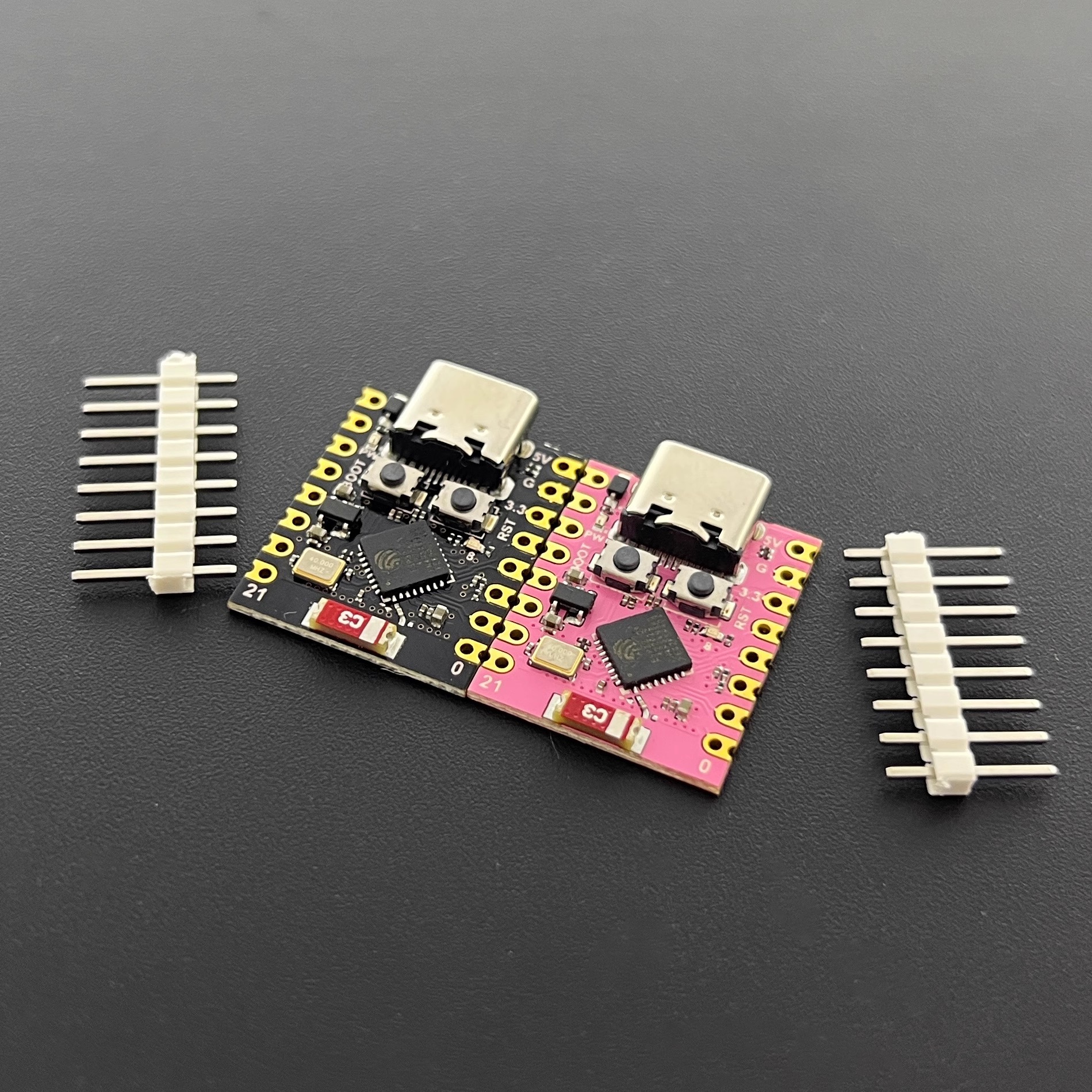
ESP32C3SuperMini is an IoT mini development board based on the Espressif ESP32-C3 WiFi/Bluetooth dual-mode chip. The ESP32-C3 is a 32-bit RISC-V CPU with FPU (Floating Point Unit) that can perform 32-bit single-precision operations, providing powerful computing capabilities. It features excellent RF performance, supporting IEEE 802.11 b/g/n WiFi and Bluetooth 5 (LE) protocols. The board comes with an external antenna to enhance signal strength for wireless applications. It also has a compact and elegant form factor with single-sided surface mount design. It is equipped with rich interfaces, including 11 digital I/O pins that can be used as PWM pins and 4 analog I/O pins that can be used as ADC pins. It supports four serial interfaces including UART, I2C, and SPI. The board also has a small reset button and a bootloader mode button.
Combining all these features, ESP32C3SuperMini is positioned as a high-performance, low-power, cost-effective IoT mini development board, suitable for low-power IoT applications and wireless wearable applications.
Hardware Description
Product Specifications
- Powerful CPU: ESP32-C3, 32-bit RISC-V single-core processor, running at up to 160 MHz
- WiFi: 802.11b/g/n protocol, 2.4GHz, supports Station mode, SoftAP mode, SoftAP+Station mode, and promiscuous mode
- Bluetooth: Bluetooth 5.0
- Ultra-low power consumption: Deep sleep power consumption about 43μA
- Rich board resources: 400KB SRAM, 384KB ROM, built-in 4MB flash
- Chip model: ESP32C3FN4
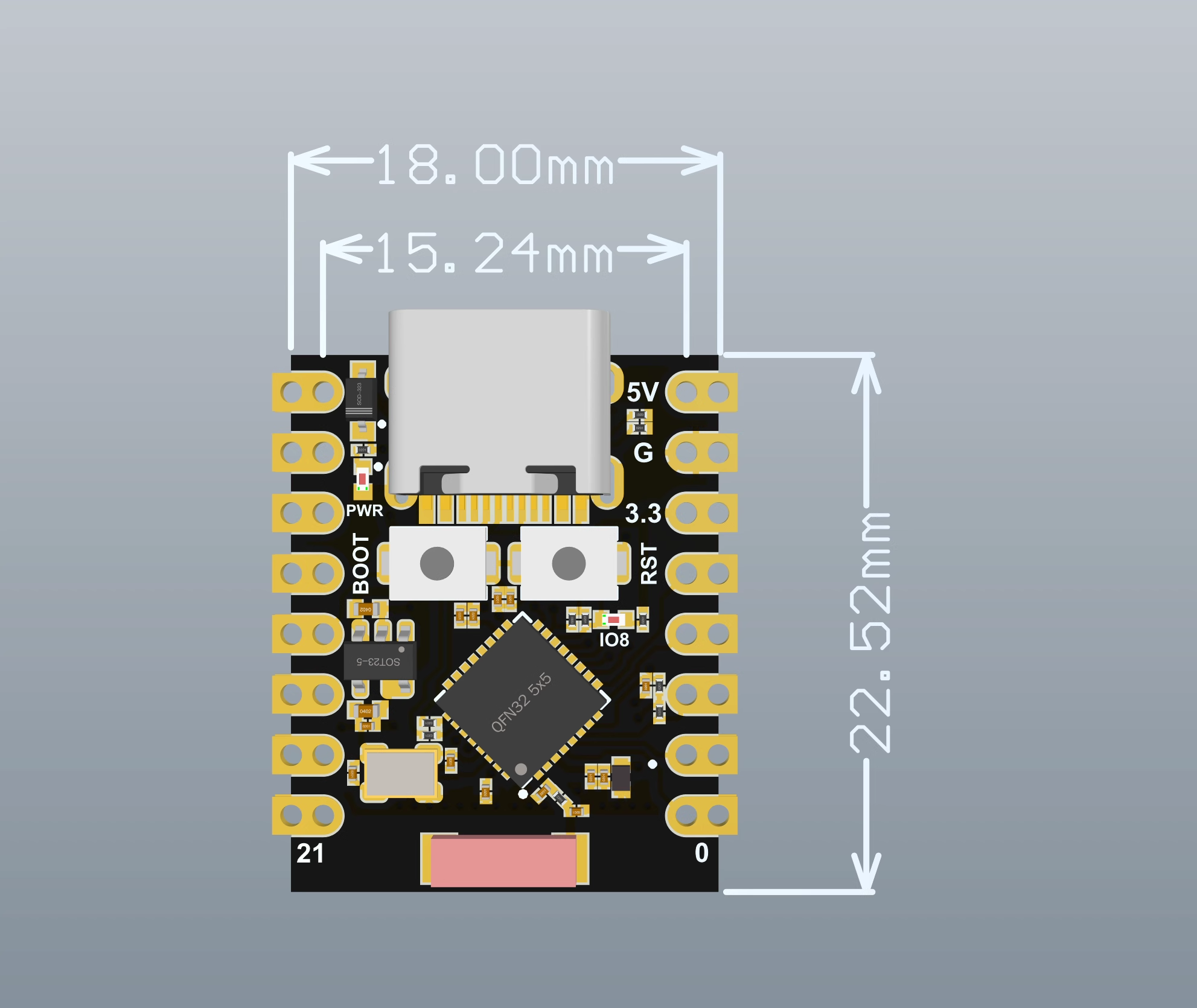
- Ultra-compact size: As small as a thumb (22.52x18mm) classic form factor, suitable for wearable devices and small projects
- Reliable security features: Hardware encryption accelerator supporting AES-128/256, hash, RSA, HMAC, digital signature, and secure boot
- Rich interfaces: 1xI2C, 1xSPI, 2xUART, 11xGPIO(PWM), 4xADC
- Single-sided components, surface mount design
- On-board blue LED: GPIO8 pin
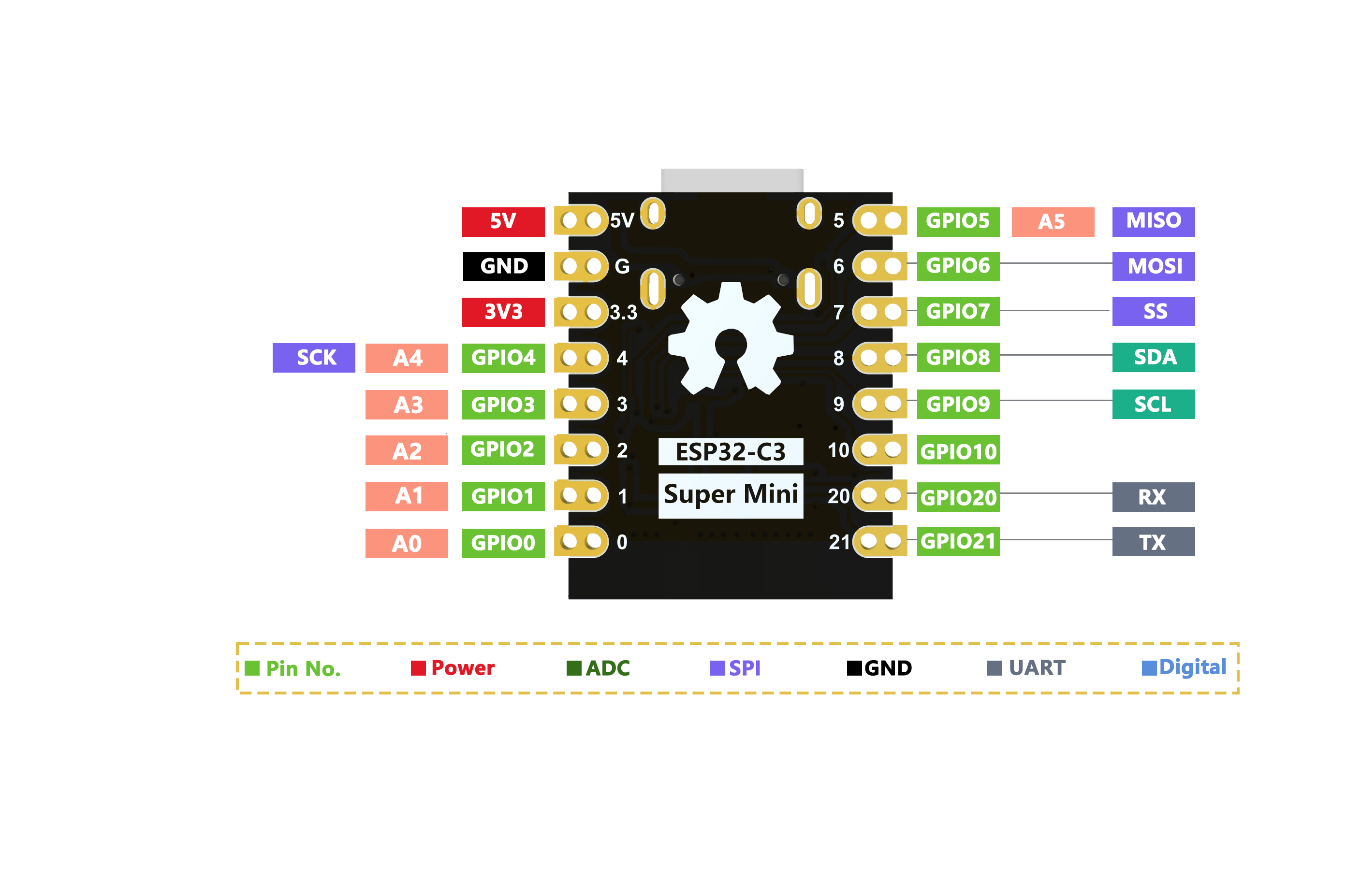
Pin Diagram
Dimension Diagram
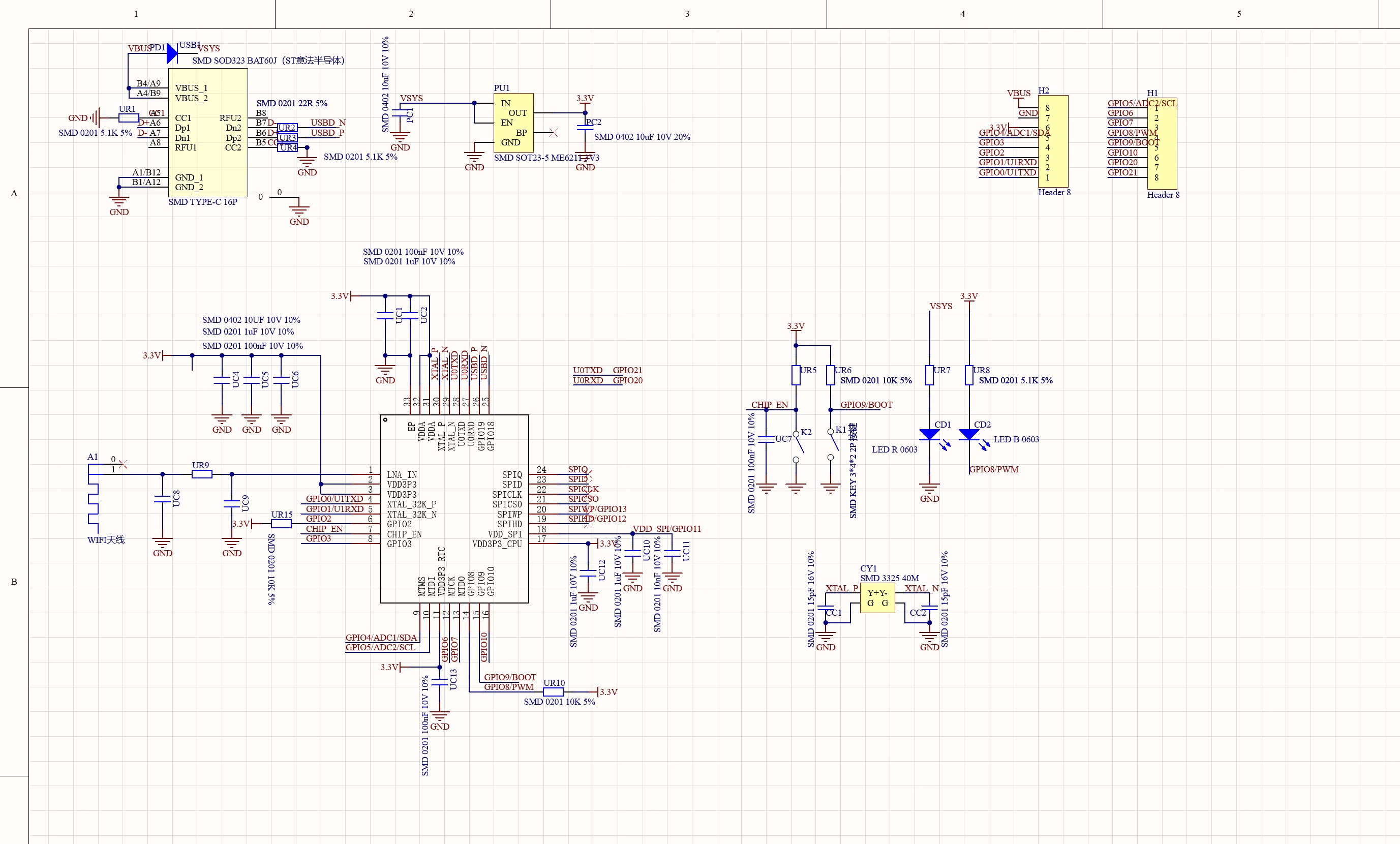
Schematic Diagram
External Power Supply
If external power supply is needed, simply connect the external power supply positive terminal to the 5V position and GND to the negative terminal. (Supports 3.3V to 6V power supply). Remember that when connecting external power supply, USB cannot be connected. USB and external power supply can only choose one.
Warning
When soldering, please be careful not to short-circuit the positive and negative terminals, which may damage the battery and device.
WiFi Antenna
If you want to use an external antenna, you can connect an external antenna according to the following image.

Getting Started
Hardware Setup
You need to prepare the following:
1 ESP32C3SuperMini
1 computer
1 USB Type-C data cable
Tips
Some USB cables can only provide power but cannot transmit data. If you don't have a USB cable or don't know if your USB cable can transmit data, you can purchase a Type-C data cable
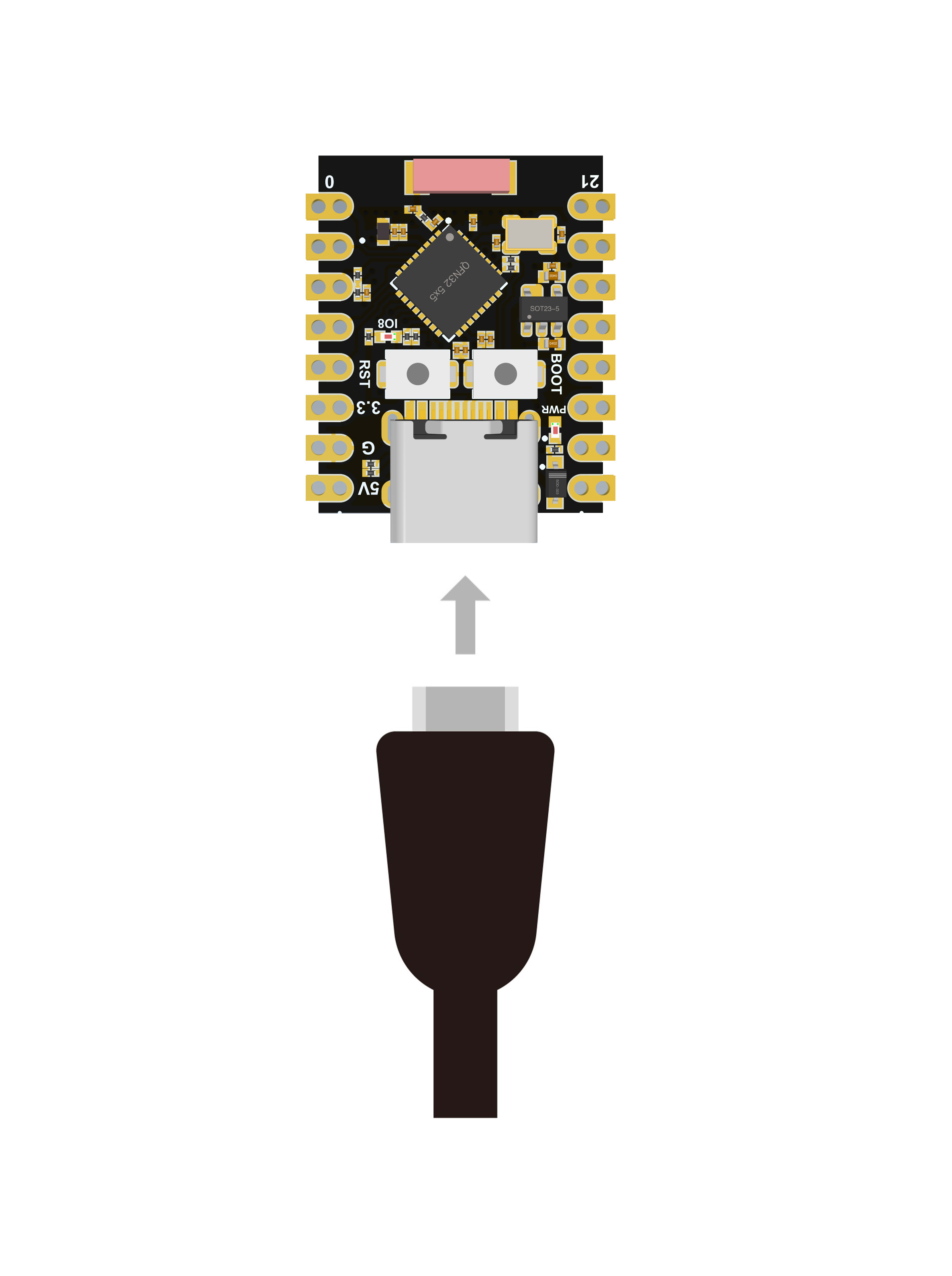
- Step 1. Connect ESP32C3SuperMini to your computer via USB Type-C data cable
Software Setup
- Step 1. Download and install the latest version of Arduino IDE according to your operating system

If the download is slow, you can download from the domestic Arduino community Arduino IDE Download Address
Step 2. Launch the Arduino application
Step 3. Add ESP32 board package to Arduino IDE
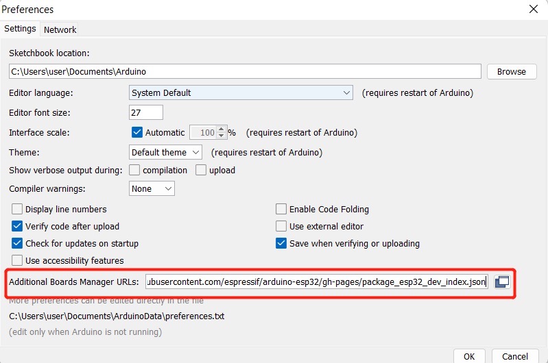
Navigate to File > Preferences ,然后使用以下 url 填写“Additional Boards Manager URL” :
https://raw.githubusercontent.com/espressif/arduino-esp32/gh-pages/package_esp32_index.json
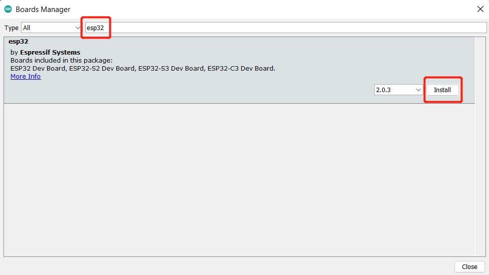
Navigate to Tools > Board > Boards Manager... ,在搜索框中输入关键字“ esp32 ”,选择最新版本的esp32并安装它。
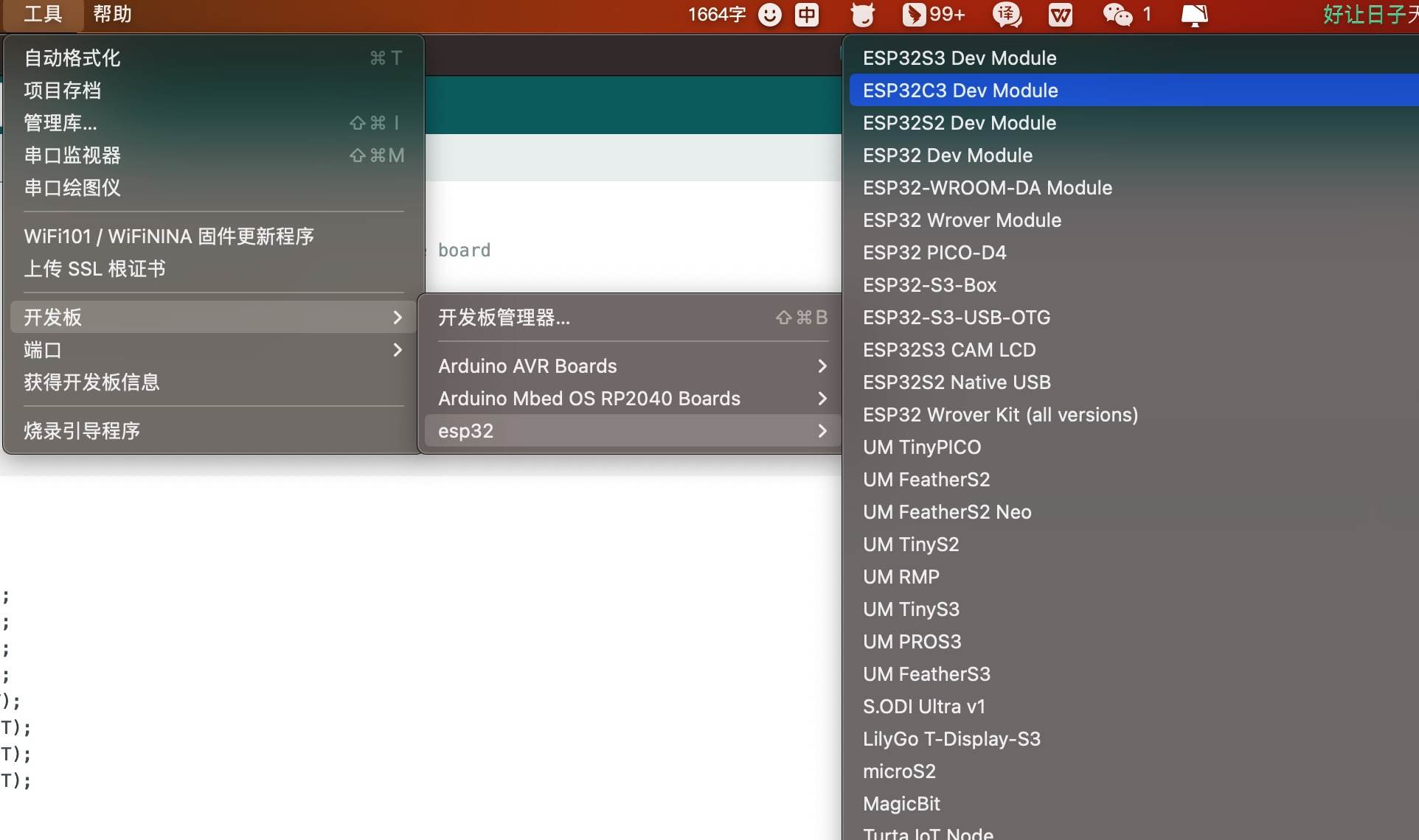
导航到工具 > 开发板 > ESP32 Arduino并选择“ ESP32C3 Dev Module ”。板的列表有点长,你需要滚动到底部才能到达它。
导航到“工具”>“端口”,然后选择所连接的 ESP32C3SuperMini 的串口名称。这可能是 COM3 或更高版本(COM1和COM2通常保留用于硬件串行端口)。
Blinking LED
Step 1. Copy the following code to Arduino IDE
// define led according to pin diagram
int led = 8;

void setup() {
  // initialize digital pin led as an output
  pinMode(led, OUTPUT);
}

void loop() {
  digitalWrite(led, HIGH);   // turn the LED off
  delay(1000);               // wait for a second
  digitalWrite(led, LOW);    // turn the LED on
  delay(1000);               // wait for a second
}
After uploading, you will see the LED on the board blinking with a 1-second delay between each blink.
WiFi Controlled LED
Example Code
/*
 WiFi Web Server LED Blink

 A simple web server that lets you blink an LED via the web.
 This sketch will print the IP address of your WiFi Shield (once connected)
 to the Serial monitor. From there, you can open that address in a web browser
 to turn on and off the LED on pin 5.

 If the IP address of your shield is yourAddress:
 http://yourAddress/H turns the LED on
 http://yourAddress/L turns it off

 This example is written for a network using WPA2 encryption. For insecure
 WEP or WPA, change the Wifi.begin() call and use Wifi.setMinSecurity() accordingly.

 Circuit:
 * WiFi shield attached
 * LED attached to pin 5

 created for arduino 25 Nov 2012
 by Tom Igoe

ported for sparkfun esp32
31.01.2017 by Jan Hendrik Berlin

 */

#include <WiFi.h>

const char* ssid     = "Onion3";  // Set WiFi name
const char* password = "asdfghjkl";  // Set WiFi password

WiFiServer server(80);

void setup()
{
    Serial.begin(115200);
    pinMode(8, OUTPUT);      // set the LED pin mode

    delay(10);

    // We start by connecting to a WiFi network

    Serial.println();
    Serial.println();
    Serial.print("Connecting to ");
    Serial.println(ssid);

    WiFi.begin(ssid, password);

    while (WiFi.status() != WL_CONNECTED) {
        delay(500);
        Serial.print(".");
    }

    Serial.println("");
    Serial.println("WiFi connected.");
    Serial.println("IP address: ");
    Serial.println(WiFi.localIP());

    server.begin();

}

void loop(){
 WiFiClient client = server.available();   // listen for incoming clients

  if (client) {                             // if you get a client,
    Serial.println("New Client.");           // print a message out the serial port
    String currentLine = "";                // make a String to hold incoming data from the client
    while (client.connected()) {            // loop while the client's connected
      if (client.available()) {             // if there's bytes to read from the client,
        char c = client.read();             // read a byte, then
        Serial.write(c);                    // print it out the serial monitor
        if (c == '\n') {                    // if the byte is a newline character

          // if the current line is blank, you got two newline characters in a row.
          // that's the end of the client HTTP request, so send a response:
          if (currentLine.length() == 0) {
            // HTTP headers always start with a response code (e.g. HTTP/1.1 200 OK)
            // and a content-type so the client knows what's coming, then a blank line:
            client.println("HTTP/1.1 200 OK");
            client.println("Content-type:text/html");
            client.println();

            // the content of the HTTP response follows the header:
            client.print("Click <a href=\"/H\">here</a> to turn the LED on pin 8 on.<br>");
            client.print("Click <a href=\"/L\">here</a> to turn the LED on pin 8 off.<br>");

            // The HTTP response ends with another blank line:
            client.println();
            // break out of the while loop:
            break;
          } else {    // if you got a newline, then clear currentLine:
            currentLine = "";
          }
        } else if (c != '\r') {  // if you got anything else but a carriage return character,
          currentLine += c;      // add it to the end of the currentLine
        }

        // Check to see if the client request was "GET /H" or "GET /L":
        if (currentLine.endsWith("GET /H")) {
          digitalWrite(8, HIGH);               // GET /H turns the LED on
        }
        if (currentLine.endsWith("GET /L")) {
          digitalWrite(8, LOW);                // GET /L turns the LED off
        }
      }
    }
    // close the connection:
    client.stop();
    Serial.println("Client Disconnected.");
  }
}
MicroPython
ESP32C3SuperMini MicroPython Firmware Download Address
MicroPython Firmware Download Tutorial
Learning Resources
Open Source Project ESP32 Arduino Tutorial
Open Source Project ESP32 MicroPython Tutorial
ESP32-C3 Official Learning Resources
ESP32-C3 Collected Learning Resources
Troubleshooting
Q1 Arduino cannot recognize COM port
Enter download mode: Method 1: Hold BOOT while powering on. Method 2: Hold the ESP32C3 BOOT button, then press the RESET button, release the RESET button, then release the BOOT button. At this time, ESP32C3 will enter download mode. (Each connection requires re-entering download mode. Sometimes pressing once, the port is unstable and will disconnect. You can judge by the port recognition sound)
Q2 Program cannot run after upload
After successful upload, you need to press the Reset button once for it to execute.
Q3 When plugged into computer, COM port is not displayed, shows (JTAG/serial debug unit)
JTAG/serial debug unit Display Solution
Q4 ESP32C3SuperMini Arduino serial port cannot print
You need to set USB CDC On Boot in the toolbar to Enabled.
For more questions and interesting applications, please visit the Forum or join QQ technical exchange group: 1054780900