ESP32C3SuperMini 入门
简介
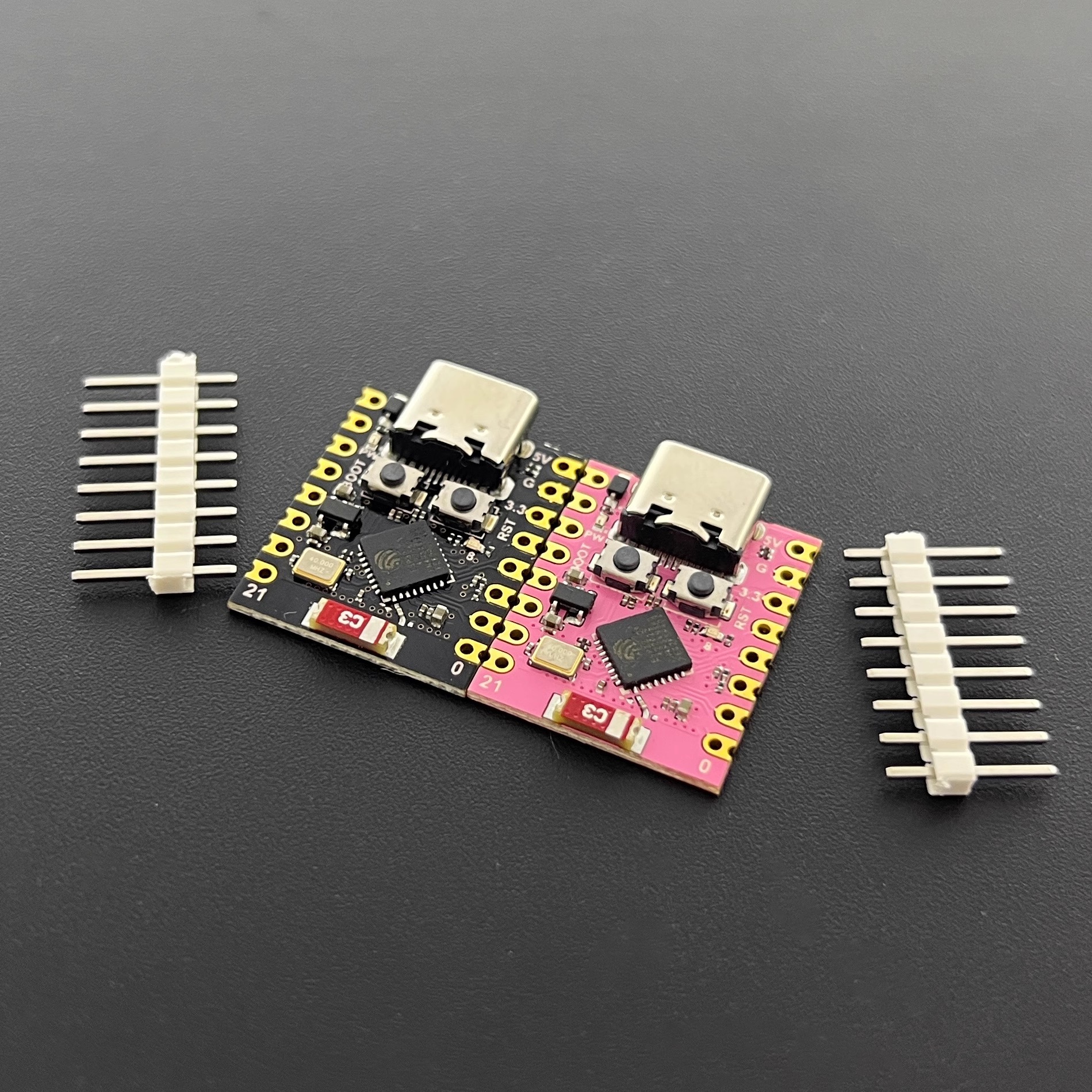
ESP32C3SuperMini是一款基于 Espressif ESP32-C3 WiFi/蓝牙双模芯片的 IoT 迷你开发板。ESP32-C3 是一款32 位 RISC-V CPU,包含FPU(浮点单元),可进行32 位单精度运算,具有强大的计算能力。它具有出色的射频性能,支持IEEE 802.11 b/g/n WiFi和蓝牙 5 (LE)协议。该板附带外部天线,可增强无线应用的信号强度。它还具有小巧精致的外形并结合单面表面贴装设计。它配备了丰富的接口,有11个可用作PWM引脚的数字I/O和4个可用作ADC引脚的模拟I/O。它支持UART、I2C 和 SPI等四种串行接口。板上还有一个小的重置按钮和一个引导加载程序模式按钮。
综合以上特点,ESP32C3SuperMini定位为高性能、低功耗、高性价比的物联网迷你开发板,适用于低功耗物联网应用和无线可穿戴应用。
硬件描述
产品参数
- 强大的 CPU:ESP32-C3,32 位 RISC-V 单核处理器,运行频率高达 160 MHz
- WiFi:802.11b/g/n协议、2.4GhHz、支持Station模式、SoftAP模式、SoftAP+Station模式、混杂模式
- 蓝牙:Bluetooth 5.0
- 超低功耗:深度睡眠功耗约43μA
- 丰富的板子资源:400KB SRAM、384KB ROM 内置4Mflash 。
- 芯片型号 :ESP32C3FN4
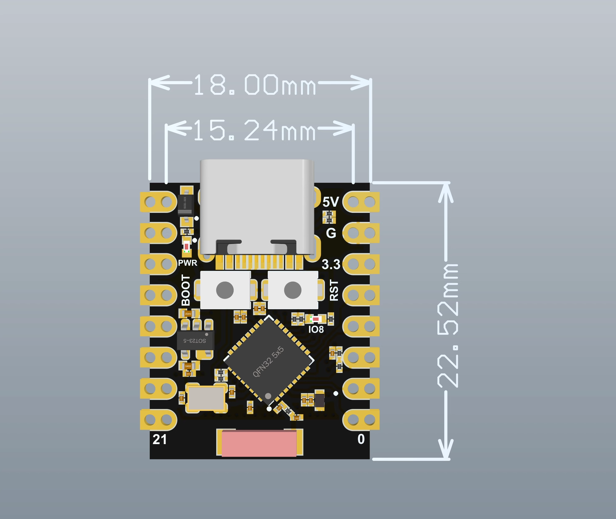
- 超小尺寸:小至拇指 (22.52x18mm) 经典外形,适用于可穿戴设备和小型项目
- 可靠的安全功能:支持 AES-128/256、哈希、RSA、HMAC、数字签名和安全启动的加密硬件加速器
- 丰富的接口:1xI2C、1xSPI、2xUART、11xGPIO(PWM)、4xADC
- 单面元件、表面贴装设计
- 板载LED蓝灯: GPIO8引脚
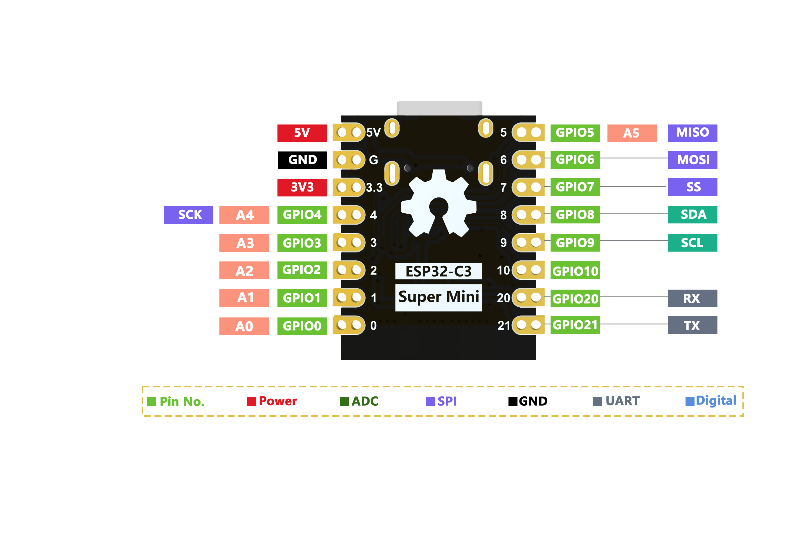
引脚图
尺寸图
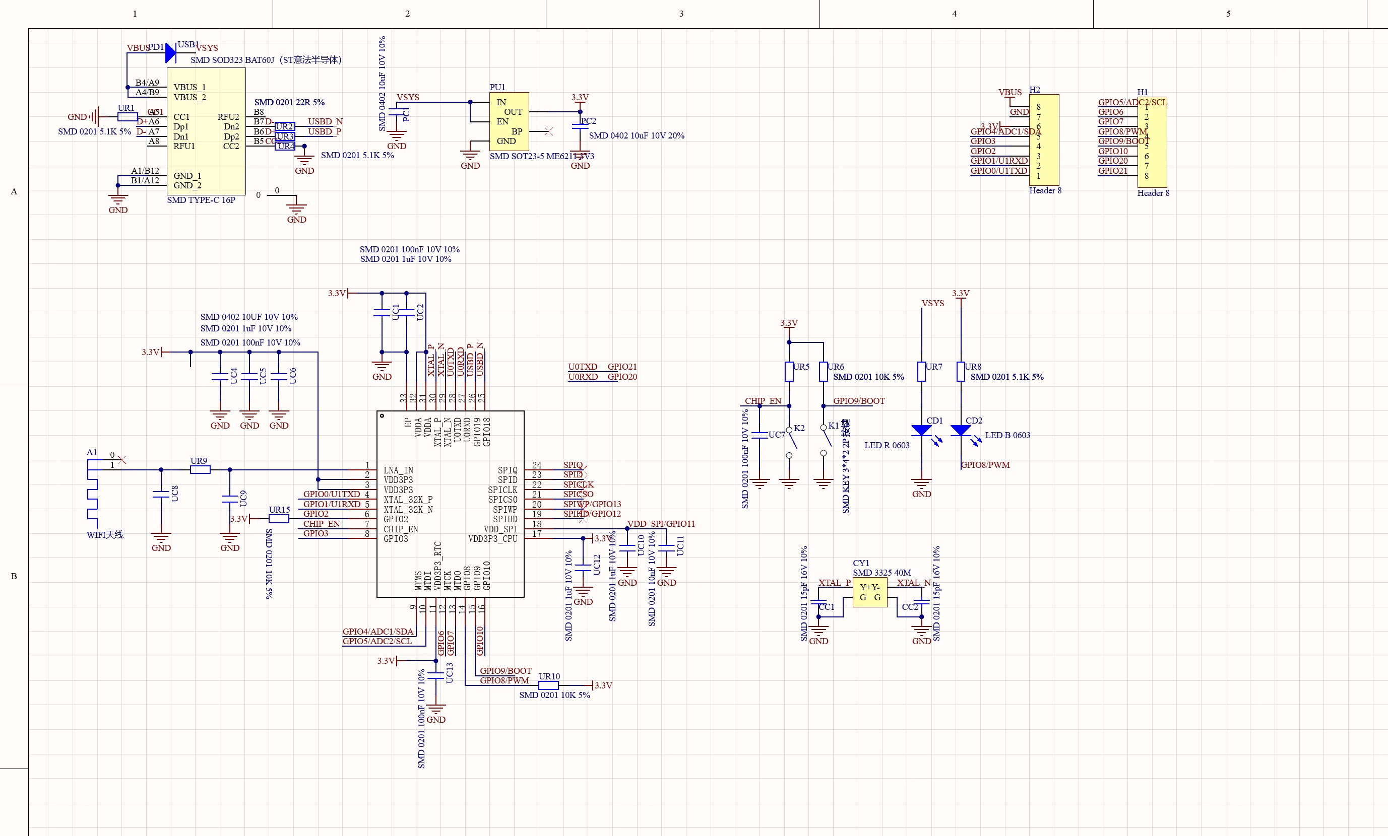
原理图
外接电源
如果需要外部供电只需将外部电源+级接入5V的位置,GND接负极。(支持3.3~6V电源)。切记连接外部电源的时候,无法接入USB,USB和外部供电只能选择一个。
注意
焊接时请注意不要使正负极短路,烧坏电池和设备。
WIFI天线
如果想使用外置天线,可以按照一下图片外接外置天线。

入门
硬件设置
您需要准备以下内容:
1 个ESP32C3SuperMini
1 台电脑
1 根 USB Type-C数据线
提示
有些USB线只能供电,不能传输数据。如果您没有 USB 线或者不知道您的 USB 线是否可以传输数据,可以购买Type-c数据线
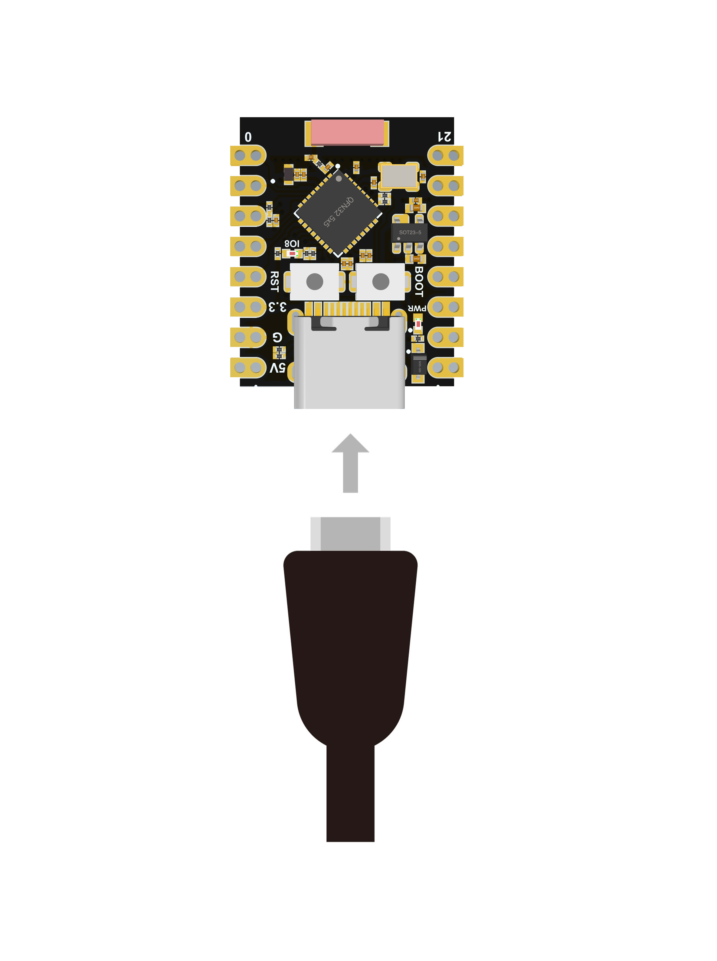
- 步骤 1.通过USB Type-C数据线将ESP32C3SuperMini连接到计算机
软件设置
- 步骤1.根据您的操作系统下载并安装最新版本的Arduino IDE

如果下载缓慢可以在国内Arduino社区下载ArduinoIDE下载地址
步骤 2.启动 Arduino 应用程序
步骤 3.将 ESP32 板包添加到 Arduino IDE
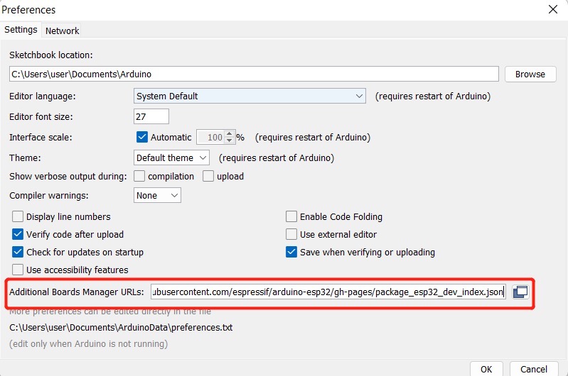
导航到File > Preferences ,然后使用以下 url 填写“Additional Boards Manager URL” :
https://raw.githubusercontent.com/espressif/arduino-esp32/gh-pages/package_esp32_index.json
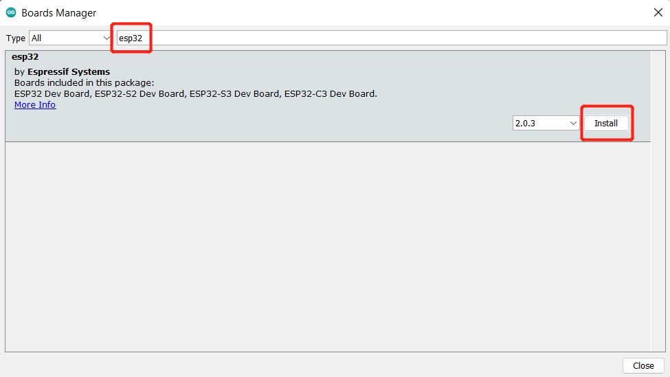
导航到Tools > Board > Boards Manager... ,在搜索框中输入关键字“ esp32 ”,选择最新版本的esp32并安装它。
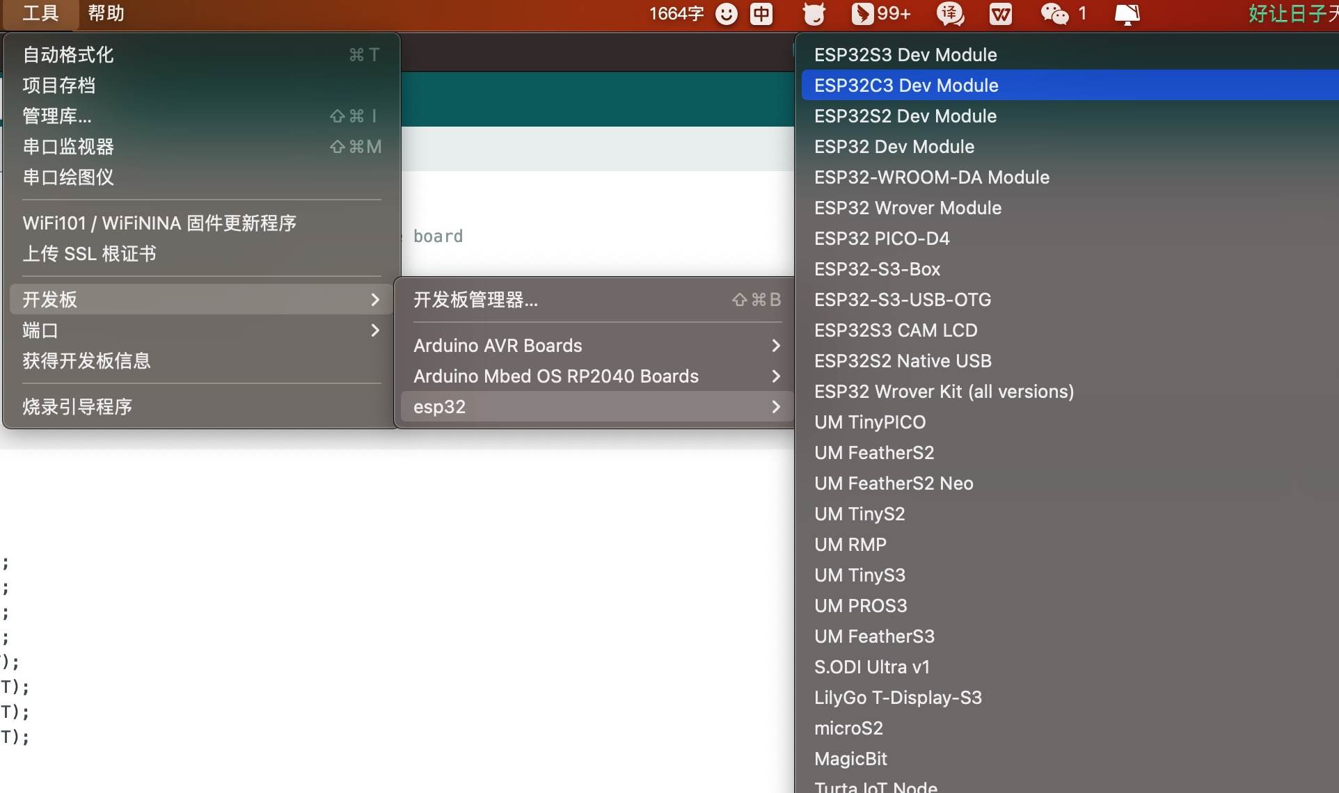
导航到工具 > 开发板 > ESP32 Arduino并选择“ ESP32C3 Dev Module ”。板的列表有点长,你需要滚动到底部才能到达它。
导航到“工具”>“端口”,然后选择所连接的 ESP32C3SuperMini 的串口名称。这可能是 COM3 或更高版本(COM1和COM2通常保留用于硬件串行端口)。
闪烁的LED
步骤1.将以下代码复制到Arduino IDE
// define led according to pin diagram
int led = 8;

void setup() {
  // initialize digital pin led as an output
  pinMode(led, OUTPUT);
}

void loop() {
  digitalWrite(led, HIGH);   // turn the LED off
  delay(1000);               // wait for a second
  digitalWrite(led, LOW);    // turn the LED on
  delay(1000);               // wait for a second
}
上传后,您将看到板子上的LED 闪烁,每次闪烁之间有 1 秒的延迟。
WIFI控制LED
示例代码
/*
 WiFi Web Server LED Blink

 A simple web server that lets you blink an LED via the web.
 This sketch will print the IP address of your WiFi Shield (once connected)
 to the Serial monitor. From there, you can open that address in a web browser
 to turn on and off the LED on pin 5.

 If the IP address of your shield is yourAddress:
 http://yourAddress/H turns the LED on
 http://yourAddress/L turns it off

 This example is written for a network using WPA2 encryption. For insecure
 WEP or WPA, change the Wifi.begin() call and use Wifi.setMinSecurity() accordingly.

 Circuit:
 * WiFi shield attached
 * LED attached to pin 5

 created for arduino 25 Nov 2012
 by Tom Igoe

ported for sparkfun esp32
31.01.2017 by Jan Hendrik Berlin

 */

#include <WiFi.h>

const char* ssid     = "Onion3";  // 设置wifi名称
const char* password = "asdfghjkl";  // 设置wifi密码

WiFiServer server(80);

void setup()
{
    Serial.begin(115200);
    pinMode(8, OUTPUT);      // set the LED pin mode

    delay(10);

    // We start by connecting to a WiFi network

    Serial.println();
    Serial.println();
    Serial.print("Connecting to ");
    Serial.println(ssid);

    WiFi.begin(ssid, password);

    while (WiFi.status() != WL_CONNECTED) {
        delay(500);
        Serial.print(".");
    }

    Serial.println("");
    Serial.println("WiFi connected.");
    Serial.println("IP address: ");
    Serial.println(WiFi.localIP());

    server.begin();

}

void loop(){
 WiFiClient client = server.available();   // listen for incoming clients

  if (client) {                             // if you get a client,
    Serial.println("New Client.");           // print a message out the serial port
    String currentLine = "";                // make a String to hold incoming data from the client
    while (client.connected()) {            // loop while the client's connected
      if (client.available()) {             // if there's bytes to read from the client,
        char c = client.read();             // read a byte, then
        Serial.write(c);                    // print it out the serial monitor
        if (c == '\n') {                    // if the byte is a newline character

          // if the current line is blank, you got two newline characters in a row.
          // that's the end of the client HTTP request, so send a response:
          if (currentLine.length() == 0) {
            // HTTP headers always start with a response code (e.g. HTTP/1.1 200 OK)
            // and a content-type so the client knows what's coming, then a blank line:
            client.println("HTTP/1.1 200 OK");
            client.println("Content-type:text/html");
            client.println();

            // the content of the HTTP response follows the header:
            client.print("Click <a href=\"/H\">here</a> to turn the LED on pin 8 on.<br>");
            client.print("Click <a href=\"/L\">here</a> to turn the LED on pin 8 off.<br>");

            // The HTTP response ends with another blank line:
            client.println();
            // break out of the while loop:
            break;
          } else {    // if you got a newline, then clear currentLine:
            currentLine = "";
          }
        } else if (c != '\r') {  // if you got anything else but a carriage return character,
          currentLine += c;      // add it to the end of the currentLine
        }

        // Check to see if the client request was "GET /H" or "GET /L":
        if (currentLine.endsWith("GET /H")) {
          digitalWrite(8, HIGH);               // GET /H turns the LED on
        }
        if (currentLine.endsWith("GET /L")) {
          digitalWrite(8, LOW);                // GET /L turns the LED off
        }
      }
    }
    // close the connection:
    client.stop();
    Serial.println("Client Disconnected.");
  }
}
Micropython
ESP32C3SuperMini Micropython固件下载地址
学习资料
疑难解答
Q1 Arduino上无法识别Com口
进入下载模式:方式1:按住BOOT上电。方式2:按住ESP32C3的BOOT按键,然后按下RESET按键,松开RESET按键,再松开BOOT按键,此时ESP32C3会进入下载模式。(每次连接都需要重新进入下载模式,有时按一遍,端口不稳定会断开,可以通过端口识别声音来判断)
Q2 上传之后程序无法运行
上传成功之后需要按一下Reset按键,才会执行。
Q3 插上电脑不显示Com口,显示 (JTAG/serial debug unit)
显示 JTAG/serial debug unit 解决方案
Q4 ESP32C3SuperMini Arduino 串口无法打印
需要将工具栏中USB CDC On Boot 设置成Enabled。
更多问题及有趣的应用,请访问论坛 或加入QQ技术交流群:522420541